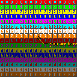
 Fig 20.1: this is your map (well, kinda) |
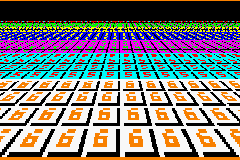 Fig 20.2: this is your map in mode7. |
| Text systems | Contents | More mode 7 |
Right, and now for something cool: mode 7. Not just how to implement it on the GBA, but also the math behind it. You need to know your way around tiled backgrounds (especially the transformable ones) interrupts. Read up on those subjects if you don't. The stuff you'll find here explains the basics of Mode 7. I also have an advanced page, but I urge you to read this one first, since the math is still rather easy compared to what I'll use there.
Way, way back in 1990, there was the Super NES, the 16bit successor to the Nintendo Entertainment System. Apart from the usual improvements that are inherent to new technology, the SNES was the first console to have special hardware for graphic tricks that allowed linear transformations (like rotation and scaling) on backgrounds and sprites. Mode7 took this one step further: it not only rotated and scaled a background, but added a step for perspective to create a 3D look.
One could hardly call Mode 7 yet another pretty gimmick. For example, it managed to radically change the racing game genre. Older racing games (like Pole Position and Outrun) were limited to simple left and right bends. Mode 7 allowed more interesting tracks, as your vision wasn't limited to the part of the track right in front of you. F-Zero was the first game to use it and blew everything before it out of the water (the original Fire Field is still one of the most vicious tracks around with its hairpins, mag-beams and mines). Other illustrious games were soon to follow, like Super Mario Kart (mmmm, Rainbow Road. 150cc, full throttle all the way through *gargle*) and Pilotwings.
Since the GBA is essentially a miniature SNES, it stands to reason that you could do Mode7 graphics on it as well. And, you'd be right, although I heard the GBA Mode7 is a little different as the SNES'. On the SNES the video modes really did run up to #7 (see the “qsnesdoc.htm” in the SNES starter kit) The GBA only has modes 0-5. So technically “GBA Mode 7” is a yet another misnomer. However, for everyone who's not a SNES programmer (which is nearly everyone, me included) the term is synonymous with the graphical effect it was famous for: a perspective view. And you can create a perspective view on the GBA, so in that sense the term's still true.
I'm not sure about the SNES, but GBA Mode 7 is a very much unlike true 3D APIs like OpenGL and Direct3D. On those systems, you can just give the proper perspective matrix and place it into the pipeline. On the GBA, however, you only have the general 2D transformation matrix P and displacement dx at your disposal and you have to do all the perspective calculations yourself. This basically means that you have to alter the scaling and translation on every scanline using either the HBlank DMA or the HBlank interrupt.
In this tutorial, I will use the 64x64t affine background from the sbb_aff demo (which looks a bit like fig 20.1), do the Mode7 mojo and turn it into something like depicted in fig 20.2. The focus will be on showing, in detail, how the magic works. While the end result is given as a HBlank interrupt function; converting to a HBlank DMA case shouldn't be to hard.
|
Fig 20.1: this is your map (well, kinda) |
Fig 20.2: this is your map in mode7. |
(If you are familiar with the basics of perspective, you can just skim
this section.)
If you've ever looked at a world map or a 3D game, you know that
when mapping from 3D to 2D, something' has to give. The technical
term for this is projection. There are many types of
projection, but the one we're concerned with is perspective,
which makes objects look smaller the further off they are.
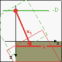
We start with a 3D space like the one in fig 20.3. In computer graphics, it is customary to have the x-axis pointing to the right and the y-axis pointing up. The z-axis is the determined by the handedness of the space: a right-handed coordinate system has it pointing to the back (out of the screen), which in a left-handed system it's pointing to the front. I'm using a right-handed system because my mind gets hopelessly confused in a left-handed system when it comes to rotation and calculating normals. Another reason is that this way the screen coordinates correspond to (x, z) values. It is also customary to have the viewer at the origin (for a different viewer position, simply translate the world in the other direction). For a right-handed system, this means that you're looking down the negative z-axis.
Of course, you can't see everything: only the objects inside the viewing volume are visible. For a perspective projection this is defined by the viewer position (the origin in our case) and the projection plane, located in front of the viewer at a distance D. Think of it as the screen. The projection plane has a width W and height H. So the viewing volume is actually a viewing pyramid, though in practice it is usually a viewing frustum (a beheaded pyramid), since there is a minimum and maximum to the distance you can perceive as well.
Fig 20.4 shows what the perspective projection actually does. Given is a point (y, z) which is projected to point (yp, −D) on the projection plane. The projected z-coordinate, by definition, is −D. The projected y-coordinate is the intersection of the projection plane and the line passing through the viewer and the original point:
| (20.1) | yp = y·D/z |
Basically, you divide by z/D. Since it is so important a factor it has is own variable: the zoom factor λ:
| (20.2) | λ = z/D= y/yp |
As a rule, everything in front the projection plane (λ<1) will be enlarged, and everything behind it (λ>1) is shrunk.
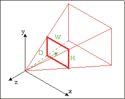 Fig 20.3: 3D coordinate system showing the viewing pyramid defined by the origin, and the screen rectangle (W×H) at z= −D |
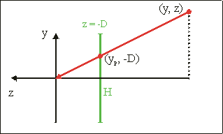 Fig 20.4: Side view; point (y, z) is projected onto the (z = −D plane. The projected point is yp = y·D/z |
Figs 20.3 and 20.4 describe the general case for perspective projection in a 3D world with tons of objects and viewer orientations. The case for Mode 7 is considerably less complicated than that:
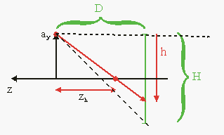 Fig 20.5: side view of Mode 7 perspective
Fig 20.5 shows the whole situation. A
viewer at y = ay is
looking in the negative z-direction. At a distance D in front
of the viewer is the projection plane, the bottom half of which is
displayed on the GBA screen of height H (=160). And now for the
fun part. The GBA doesn't have any real 3D hardware capabilities, but
you can fake it by cleverly manipulating the scaling and translation
REG_BGxX-REG_BGxPD for every scanline. You just have to
figure out which line of part of the floor goes into which scanline,
and at which zoom level. Effectively, you're building a very simple
ray-caster.
Conceptually, there are four steps to Mode 7, depicted in figs 20.6a-d. Green figures indicate the original map; red is the map after the operation. Given a scanline h, here's what we do:
| (20.3) |
|
| 
| 
| 
|
| 20.6a: pre-translate by (ax, az) | 20.6b: rotate by α | 20.6c: scale by 1/λ | 20.6d: post-translate by (xs, ys) |
While the steps described above are indeed the full procedure, there are still a number of loose ends to tie up. First of all, remember that the GBA's transformation matrix P maps from screen space to background space, which is actually the inverse of what you're trying to do. So what you should use is:
| (20.4) | P = S(λ) · R(α) = |
|
And yes, the minus sign is correct for a counter-clockwise rotation (R is defined as a clockwise rotation). Also remember that the GBA uses the following relation between screen point q and background point p:
| (20.5) | dx + P · q = p , |
that is, one translation and one transformation. We have to combine the pre- and post-translations to make it work. We've seen this before in eq 4 in the affine background page, only with different names. Anyway, what you need is:
| (20.6) |
|
So for each scanline you do the calculations for the zoom, put the
P matrix of eq 20.4 into
REG_BGxPA-REG_BGxPD, and
a−P·xs into REG_BGxX and
REG_BGxY and presto! Instant Mode 7.
Well, almost. Remember what
happens when writing to REG_BGxY inside an HBlank
interrupt: the current scanline is perceived as the
screen's origin null-line. In other words, it does the
+h part of ys automatically. Renaming
the true ys to ys0, what
you should use is
| (20.7) | ys = ys0−h = D. |
Now, in theory you have everything you need. In practice, though, there are a number of things that can go wrong. Before I go into that, here's a nice, (not so) little demo.
As usual, there is a demo. Actually, I have several Mode 7 demos, but that's not important right now. The demo is called m7_demo and the controls are:
| D-pad | Strafe. |
|---|---|
| L, R | turn left and right (i.e., rotate map right and left, respectively) |
| A, B | Move up and down, though I forget which is which. |
| Select | Switch between 3 different Mode7 types (A, B, C) |
| Start | Resets all values (a= (256, 32, 256), α= 0) |
“Switch between 3 different Mode7 types”? That's what I said, yes. Make sure you move around in all three types. Please. There's a label in the top-left corner indicating the current type.
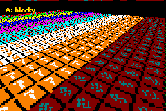 Fig 20.7a: Type A: blocked. |
 Fig 20.7b: Type B: sawtooth. |
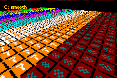 Fig 20.7c: Type C: smooth. | |
Fiddled with my demo a bit? Good. Noticed the differences between the three types? Even better! For reference, take a look at Figs 20.7a-c, which correspond to the types. They adequately show what's different.
So we have three very different Mode7 results, but I guarantee you it's all based on the same math. So how come one method looks so crummy, and the other looks great?
Here are the two HBlank ISRs that create the types. Types A and B are nearly identical, except for one thing. Type C is very different from the others. If you have a thing for self-torture, try explaining the differences from the code alone. I spent most of yesterday night figuring out what made Type C work, so I have half a mind of leaving you hanging. Fortunately for you, that half's asleep right now.
#define M7_D   128

extern VECTOR cam_pos;          // Camera position
extern FIXED g_cosf, g_sinf;    // cos(phi) and sin(phi), .8f
// --- Type A ---
// (offset * zoom) * rotation
// All .8 fixed
void m7_hbl_a()
{
    FIXED lam, xs, ys;

    lam= cam_pos.y*lu_div(REG_VCOUNT)>>16;  // .8*.16/.16 = .8

    // Calculate offsets (.8)
    xs= 120*lam;
    ys= M7_D*lam;

    REG_BG2PA= (g_cosf*lam)>>8;
    REG_BG2PC= (g_sinf*lam)>>8;

    REG_BG2X = cam_pos.x - ( (xs*g_cosf-ys*g_sinf)>>8 );
    REG_BG2Y = cam_pos.z - ( (xs*g_sinf+ys*g_cosf)>>8 );
}
// --- Type B ---
// (offset * zoom) * rotation
// Mixed fixed point: lam, xs, ys use .12
void m7_hbl_b()
{
    FIXED lam, xs, ys;

    lam= cam_pos.y*lu_div(REG_VCOUNT)>>12;  // .8*.16/.12 = .12

    // Calculate offsets (.12f)
    xs= 120*lam;
    ys= M7_D*lam;

    REG_BG2PA= (g_cosf*lam)>>12;
    REG_BG2PC= (g_sinf*lam)>>12;

    REG_BG2X = cam_pos.x - ( (xs*g_cosf-ys*g_sinf)>>12 );
    REG_BG2Y = cam_pos.z - ( (xs*g_sinf+ys*g_cosf)>>12 );
}
// --- Type C ---
// offset * (zoom * rotation)
// Mixed fixed point: lam, lxr, lyr use .12
// lxr and lyr have different calculation methods
void m7_hbl_c()
{
    FIXED lam, lcf, lsf, lxr, lyr;

    lam= cam_pos.y*lu_div(REG_VCOUNT)>>12;  // .8*.16 /.12 = 20.12
    lcf= lam*g_cosf>>8;                     // .12*.8 /.8 = .12
    lsf= lam*g_sinf>>8;                     // .12*.8 /.8 = .12

    REG_BG2PA= lcf>>4;
    REG_BG2PC= lsf>>4;

    // Offsets
    // Note that the lxr shifts down first!

    // horizontal offset
    lxr= 120*(lcf>>4);      lyr= (M7_D*lsf)>>4;
    REG_BG2X= cam_pos.x - lxr + lyr;

    // vertical offset
    lxr= 120*(lsf>>4);      lyr= (M7_D*lcf)>>4;
    REG_BG2Y= cam_pos.z - lxr - lyr;
}
All three versions do the following things: calculate the zoom-factor λ, using eq 2 and a division LUT, calculate the affine matrix using λ and stored versions of cos(φ) and sin(φ), and calculate the affine offsets. Note that only pa and pc are actually calculated; because the scanline offset is effectively zero all the time, pb and pd have no effect and can be ignored. Those are the similarities, but what's more interesting are the differences:
| h | 1/h | λ (true) | λ(.8) |
|---|---|---|---|
| 157 | 0.01a16d..h | 0.342da7h | 0.34h |
| 158 | 0.019ec8..h | 0.33d91dh | 0.33h |
| 159 | 0.019c2d..h | 0.3385a2h | 0.33h |
| 160 | 0.019999..h | 0.333333h | 0.33h |
These two (well, 2 and a half, really) differences are enough to explain the differences in the results. Please remember that the differences in the code are quite subtle: fixed point numbers are rarely used outside consoles, and results changing due to the order of calculation is probably even rarer. Yet is these two items that make all the difference here.
Let's start with types A and B, which differ only by the
fixed-point of lam. λ is the ration of the camera
height and the scanline, which will often be quite small –
smaller than 1 at any rate. Table 20.1
shows a few of the numbers.
Note that using a λ with only 8 fractional bits means that
you'll often have the same number for multiple scanlines, which
carries through in the later calculations. This is why type A, which
plays by the rules and uses a constant fixed-point like a good little
boy, is so blocky at low altitudes. The four extra bits of type B
gives much better results. Rules are nice and all, but sometimes they
needs to be broken to get results.
Now, you will notice that type B still has a bit of distortion, so
why only go to .12 fixeds in type B, why not 16? Well, with 16 you can
get into trouble with integer overflow. It'd be alright for calculating
xs and ys, but we still have to rotate these
values later on as well. OK, so we'll use 64bit math, then the 32bit
overflow wouldn't matter and we could use even more fixed point
bits! After all, more == better, right?
Well, no. Bigger/stronger/more does not always mean better (see the DS vs PSP). The remaining distortion is not a matter of the number of fixed-point bits; not exactly. You could use a 128bit math and .32f division and trig tables for all I care; it wouldn't matter here, because that's not were the problem is.
The problem, or at least part of it, is the basic algorithm used in
types A and B. If you look back to the theory, you'll see that the
affine matrix is calculated first, then the offsets. In other words,
first combine the scale and rotation, then calculate the
offset-correction, P·xs. This is how the
affine parameters in the GBA work anyway.
However, this is actually only the first step. If you follow that
procedure, you'd still get the jagged result. The real reason
for these jaggies is the order of calculation of lxr.
// Multiply, then shift to .8 (A and B)
    lxr= (120*lcf)>>4;

// Shift to .8 first, then multiply (C)
    lxr= 120*(lcf>>4);
Getting lxr = pa/c·xs
requires two parts: multiplication with P elements and the
shift down to .8 fixeds. You might expect doing the shift last would
be better because it has a higher precision. The funny thing is that
it doesn't! Shifting pa or pc
down to 8 fractional bits before the multiplication is what gets rid
of the remaining distortions, reversing the order of operations
doesn't.
As for why, I'm not 100% sure, but I can hazard a guess. The affine transformation takes place around the origin of the screen, and to place the origin somewhere else we need to apply a post-translation by xs. The crucial point I think is that xs is a point in screen-space which uses normal integers, not fixed points. However, it only applies to xs because that really represents an on-screen offset; ys is actually not a point on the screen but the focal distance of the camera. On the other hand, it might have something to do with the internal registers for the displacement.
Obviously, type C is the one you want. It really bugs the hell out
of me that I didn't think of it myself. And the fact that I
did use the scale-rotation multiplication but abandoned it
because I screwed up with the multiplication by the projection
distance D doesn't help either (yes, this sentence makes
sense). The code of m7_hbl_c shown above works,
even though it only uses 32-bit math. As long as you do the
scale-rotation multiplication first and shift down to .8 fixeds
before you multiply by 120 in the calculation of wxr
everything should be fine.
This has been one of those occasions that show that programming (especially low-level programming) is as much of a science as an art. Even though the theory for the three mode 7 versions was the same, the slight differences in the order and precision of the calculations in the implementations made for very noticeable differences in the end result. When it comes to mode 7, calculate the affine matrix before the correction offset. But most importantly, the x-offset for the screen should not be done in fixed point.
Secondly, this was only the basic theory behind mode 7 graphics. No sprites, no pitch-angle and no horizon, and tailored to the GBA hardware from the start. In the next chapter, we'll derive the theory more extensively following standard 3D theory with linear algebra. This chapter will also show how to position sprites in 3D and how to do other things with them like animating for rotation and sorting, and also present variable-pitch and a horizon. If this sounds complicated, well, I supposed that it is. It's definitely worth a look, though.
| Prev | Contents | Next |
| Text systems | More mode 7 |